Gas engine technology - Methods and equipment
Simulation methods in the GenLab
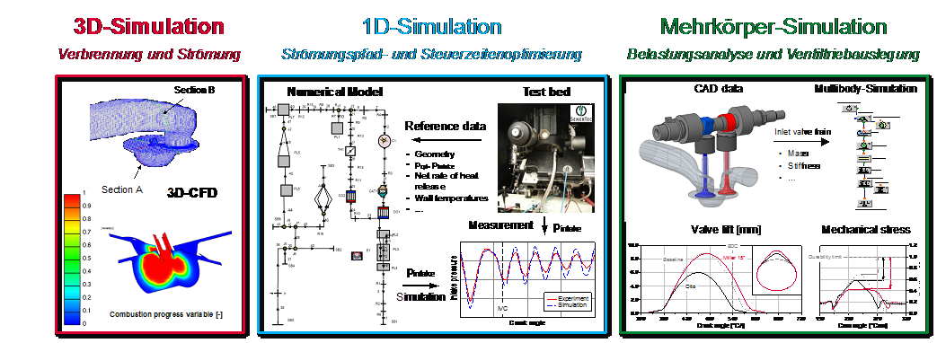
In almost all research projects of the Gas Engine Laboratory, experimentation and simulation are closely interlinked. On the basis of extensive measurement data, virtual images - "digital twins" - of the real test vehicles are created in various modeling stages and used to address scientific questions. Starting with basic simulations of ignition delay times and flame velocities using 0D simulation, the level of detail is increased via 1D engine process models to coupled 3D simulation of combustion chamber flow, combustion (3D CFD) and heat conduction in (moving) combustion chamber components (FEM) (à Conjugate Heat Transfer - CHT). In addition to the 1D engine process simulation, multi-body simulation models (MBS) of the valve train are used, which allow statements to be made regarding the mechanical loading of valve train components and are used to determine grinding coordinates for the production of optimized cam profiles. Detailed tuning of the simulation models allows "generalizing" models to be generated that can reproduce and predict real engine behavior. Extensive parameter studies can thus be carried out cost- and time-efficiently using virtual prototypes. Target configurations can be determined from the simulation data and validated with a minimum number of real prototypes on the test bench. Furthermore, detailed simulation models allow analyses of physical phenomena that are difficult or impossible to measure.
Our simulation solutions are used as part of n AVL's University Partnership Program.
To the simulation software from AVL: Simulation Solutions
Altitude and climate simulation chamber for the use of small engines and power tools with alternative fuels

The focus for the use of the environmental simulation chamber is the development of tailor-made bio-gasolines especially for use in small engines, e.g. in hand-held devices. Unlike currently available appliance gasolines, which are based exclusively on fossil raw materials, the bio-appliance gasoline is to be produced using up to 100% renewable raw materials. Before a market introduction of the new bio fuel, it applies to examine and evaluate this for its ecological, economical and engine suitability.
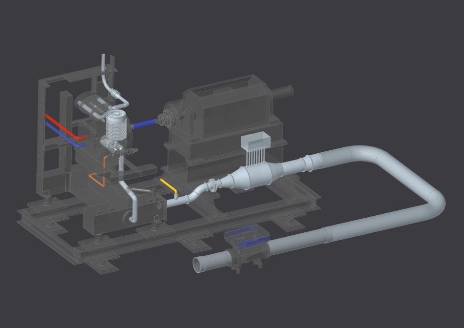
In this context, the suitability for the climatic conditions common to hand-held equipment (e.g., timber harvesting in winter) and use at high altitudes (e.g., working in the mountains) must be examined in particular. In order to realize worldwide user-relevant environmental conditions (different climatic zones and geodetic heights), an engine test bench with a climatic/altitude chamber in which temperature, pressure and humidity can be conditioned is being specially developed for this research project. It thus enables engine tests to be carried out under conditions ranging from arctic cold to tropical heat. Simulation of different altitudes (from 0 m to 3000 m a.s.l.) is also possible in the 6 m³ test cell, as shown as a CAD model in the following figures.
The goal is to conduct emission tests when using the developed fuel formulations in small engines and to work out technological innovation potentials, such as a reduction of emissions, which result, for example, from an extension of the combustion limits or higher knock resistance as well as lower self-ignition tendency.
Four-cylinder HMG-4900 cc - engine test bench
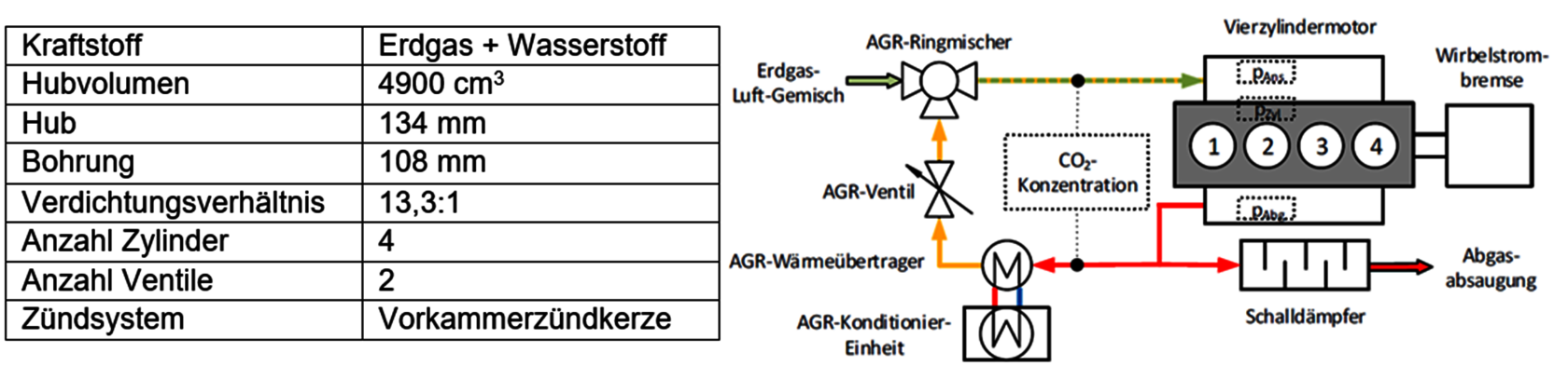
The test vehicle is a mixture-intake homogeneously lean-burn four-cylinder Otto gas engine HMG 434 S 132A from WJ Power, which is used in CHP units in the 35 kWel power class. The gas engine is derived from a basic engine originally developed as a diesel unit by Sisu, which is mainly used in commercial vehicles. In order to accelerate combustion and reduce its cyclic fluctuations in lean-burn operation, ignition is initiated via a (non-purged) prechamber spark plug. In the standard configuration, the compression ratio is e = 13.3 with a displacement of 1.2 l/cylinder. The engine is operated in the 50 Hz network at a constant speed of 1500 1/min.
In a completed research project, the test vehicle was equipped with an exhaust gas recirculation system that enables the temperature of the recirculated exhaust gas to be specified by means of conditioning. The technical data of the test vehicle and a schematic of the gas path can be found in Figure 4.
Single cylinder HCCI gas engine test bench
As part of the HCCI project, a single-cylinder research test rig equipped with extensive measurement technology was set up on the basis of a small natural gas CHP unit to investigate various combustion processes and fuels. With the help of the test stand, alternative combustion processes (HSACI, HSASI, HCCI) as well as alternative fuels (liquid, gaseous) can be investigated in a broad operating spectrum. Various (add-on) components are available for the test stand, which can be combined to form different test stand set-up stages depending on the requirements of the current projects. Against the background of power-to-gas technologies and operation with increased hydrogen contents in the fuel gas, an additional extraction system for hydrogen-bearing components was set up. In particular, the extensive indexing measurement technology allows the collection of a comprehensive database which, in addition to the analysis of physical relationships, is used to tune detailed simulation models. The test bench setup based on a state-of-the-art production engine and the use of prototype components based on near-production components enable a simplified transfer of the research results to practical applications.
Overview
- Free programmable control unit for data acquisition and test bench control
- Speed and load control (fired, towed)
- Inlet air conditioning (temperature up to 200 °C, pressure)
- Cooling water conditioning
- External, internal exhaust gas recirculation
Measurement technology
- Time-resolved acquisition of fluid temperatures and pressures
- Cylinder pressure indexing
- Low pressure indexing (inlet, outlet)
- Indication of air mass flow
- Gas chromatography for determination of natural gas components up to C6
- Exhaust gas analysis (HC, CO, NO, NO2)
Ingnition systems
- Hooked spark plug
- Pre-chamber spark plug
- glow plug ignition
- Built-in ignition systems, e.g. LINK HSASI
Mixture formation and fuels
- Injection of hydrogen on the intake side using an electrolyzer without intermediate storage ("real-time" electrolysis)
- Liquid fuel and water injection (intake manifold)
- Natural gas
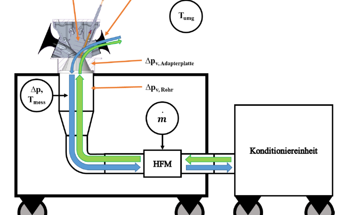
Water injection - CHP test bench engine
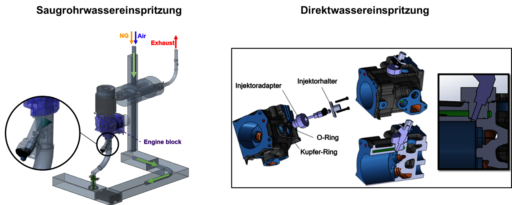
The CHP test bench engine is a unit based on the SenerTec Badger 5.5 Generation 1.1, which was modified for the water injection investigations and does not correspond to the current series engine in some respects (upper figure: configurations of water injection at GenLab).
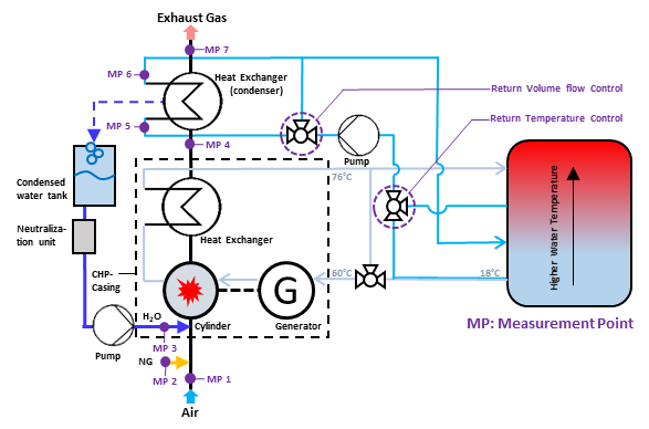
The single-cylinder naturally aspirated engine operates permanently unthrottled at a constant engine speed of n = 2450 rpm and produces 5.5 kW of electrical power in its series mode (equivalent to IMEP = 6.34 - 6.35 bar). With a relative air-fuel ratio of lambda = 1.55 and a fixed ignition timing IT = -8 °CA, MFB50 (50% of the fuel mass burned over one engine cycle) occurs at 19.7 °CA after top dead center, resulting in NOx emissions of approximately 1.44 g/kWh. The engine test bench was permitted with extensive measurement equipment (lower figure: Measurement point plan from the single-cylinder CHP engine test bench for the experimental investigations on water injection).
Injection jet test bench

The development and optimization of modern injection systems for internal combustion engines requires the use of highly accurate analysis tools as well as experimental investigations on optically accessible engines or test benches under engine-like conditions. Therefore, an injection jet test bench was developed and built at GenLab (Figure: Injection jet test bench of the GenLab research area).
The bottom of the flow channel is an adjustable aluminum profile that can be heated by two contact heaters with a heating power of 1.55 W/cm2 and a total area of 45 cm2. A pivoting structure allows evaluation of the influence of different injection angles on the interaction between the injection jet and the flow. Analogous to engine tests, water was injected under the influence of compressed air, the pressure level of which was adjusted using a high-precision LRP-1/4-10 pressure control valve from Festo. The air mass flow rate and temperature through the flow channel of the test rig were set with the engine intake air conditioning unit and monitored with a Bosch HFM5-4.7 hot film air flow meter and a type K thermocouple at the MP measuring point in Figure 1. Spray images were captured using a monochromatic CCD camera with a resolution of 9 megapixels and a maximum frame rate of 7 fps. The camera is mounted on an adjustable tripod that allows horizontal and vertical displacement. Camera settings were made using SVCapture software (SVS-Vistek). A Büchner HI-LIGHT-120 infrared light source was used for high-contrast spray images. In addition, an infrared filter was coupled to the lens to reduce distortion caused by other wavelengths of ambient light. Control of the injection jet test stand and data acquisition were performed using an ADwin Gold II unit and LABVIEW software.
![[Translate to English:] Constant Volume Combustion Chamber](/fileadmin/_processed_/7/d/csm_HKA_WE-IKKU_Imagefoto_GenLab_CVCC_a0897651c5.jpg "[Translate to English:] Constant Volume Combustion Chamber")
![[Translate to English:] Ein-Zylinder - 232 ccm - Motorenprüfstand](/fileadmin/_processed_/f/4/csm_HKA_WE-IKKU_Imagefoto_GenLab_Ausstattung_Einzylinder-Motorenpruefstand__Basis_Hatz_1B20__af67167478.png "[Translate to English:] Ein-Zylinder - 232 ccm - Motorenprüfstand")